Power Quality
Electrical equipment is designed to operate on electrical power that is at a specific voltage and frequency and relatively free from quality problems, such as voltage spikes and harmonics. Power quality problems can reduce the performance and shorten the life of electrical equipment and increase operating cost of business.
Power quality problems can be caused by a variety of conditions. A well designed power monitoring system is essential to identifying problems and quickly resolving them before they become costly.
This course will help you better understand the types of power quality problems that commonly occur in various types of facilities and how power monitoring products and systems can help you minimize these problems. First, however, there are some basics concepts that we need to cover.
Direct Current (DC)
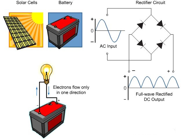
The supply of current for electrical devices may come from a direct current (DC) source or an alternating current (AC) source. As discussed in the Basics of Electricity course, electric utilities generate and distribute AC power. However, there are many sources and uses of DC power as well. DC power sources include a variety of devices such as solar cells, batteries, electronic circuits that convert AC to DC, and DC generators.
In a DC circuit, electrons flow continuously in one direction from the source of power through a conductor to a load and back to the source of power. Voltage polarity for a direct current source remains constant.
Alternating Current (AC)
An AC generator makes electrons flow first in one direction then in another. In fact, an AC generator reverses its terminal polarities many times a second, causing current to change direction with each reversal.
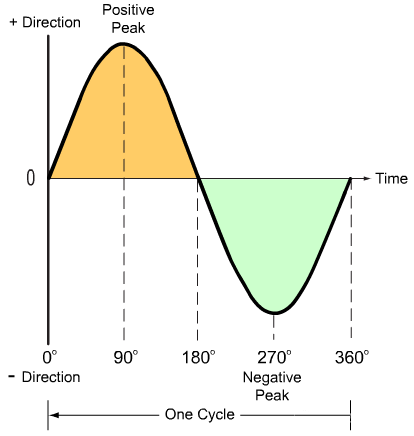
Alternating voltage and current vary continuously. The graphic representation for AC is a sine wave. A sine wave can represent current or voltage. The accompanying illustration shows one cycle of a sine wave on a graph with two axes. The vertical axis represents the direction and magnitude of current or voltage. The horizontal axis represents time.
When the waveform is above the time axis, current is flowing in one direction. This is referred to as the positive direction. When the waveform is below the time axis, current is flowing in the opposite direction. This is referred to as the negative direction.
A sine wave moves through a complete rotation of 360 degrees, which is referred to as one cycle. As will be discussed later in this course, a typical AC sine wave goes through many of these cycles each second.
requency
The number of cycles per second of voltage and current produced by an AC generator is referred to as the frequency of that voltage and current. The recognized unit for frequency is hertz, abbreviated Hz. 1 Hz is equal to 1 cycle per second.
Power companies generate and distribute electricity at very low frequencies. The standard power line frequency in the United States and many other countries is 60 Hz. 50 Hz is the other common power line frequency used throughout the world. The following illustration shows 15 cycles in 1/4 second. This is equivalent to 60 Hz.
Although power companies generate electricity at a low fixed frequency, many electronic circuits convert this low frequency to a higher frequency or a variable frequency for use in a variety of ways.
Frequency is an important characteristic of AC because many devices and circuits respond differently to different frequencies.

Amplitude
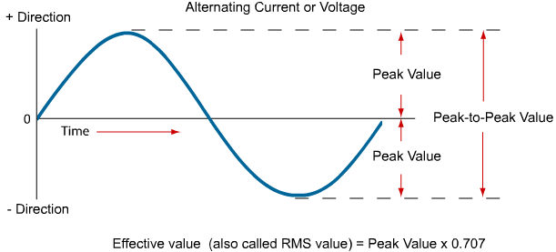
Voltage and current in an AC circuit rise and fall over time in a pattern referred to as a sine wave. As previously discussed, one complete sine wave is referred to as a cycle, and the number of cycles in one second is referred to as the frequency. In addition to frequency, an AC sine wave also has amplitude, which is the range of variation from its maximum value to its minimum value. Amplitude can be specified in three ways: peak value, peak-to-peak value, and effective value.
The peak value of a sine wave is the maximum value for each half of the sine wave.
The peak-to-peak value is the range from the positive peak to the negative peak. This is twice the peak value.
The effective value of AC is defined in terms of an equivalent heating effect when compared to DC. Instruments designed to measure AC voltage and current usually display the effective value. The effective value of an AC voltage or current is approximately equal to 0.707 times the peak value.
The effective value is also referred to as the RMS value. This name is derived from the root-mean-square mathematical process used to determine the effective value of a waveform.
Instantaneous Value
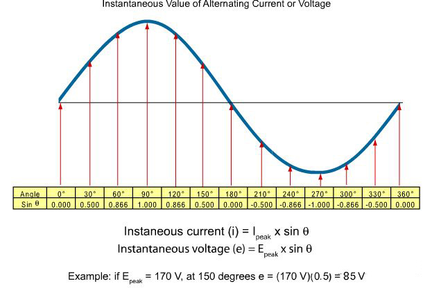
The instantaneous value is the value at any one point on the sine wave. The voltage waveform produced as the armature of a basic two-pole AC generator turns through one full 360 degree rotation is called a sine wave because the instantaneous voltage or current is related to the sine trigonometric function.
As shown in the accompanying illustration, the instantaneous voltage (e) and current (i) at any point on the sine wave is equal to the peak value times the sine of the angle. The sine values shown in the illustration are obtained from trigonometric tables. Keep in mind that each point has an instantaneous value, but this illustration only shows the sine of the angle at 30 degree intervals.
Three-Phase Power
Up till now, we have been talking only about single-phase AC power. Single-phase power is used where power demands are relatively small, such as for a typical home.
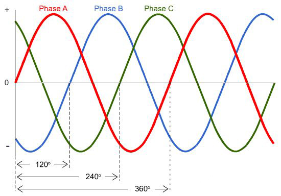
However, power companies generate and distribute three-phase power. Three-phase power is used in commercial and industrial applications where power requirements are higher than those of a typical residence.
Three-phase power, as shown in the accompanying illustration, is a continuous series of three overlapping AC cycles. Each wave represents a "phase" and is offset by 120 electrical degrees from each of the two other phases. The three phases are referred to as Phases A, B, and C.
Phase Rotation
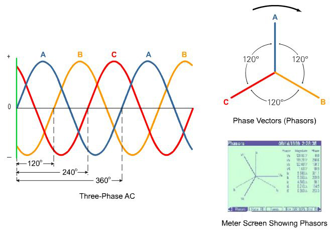
As previously described, the phase relationships for the typical three-phase AC voltage or current supplied by a power company can be shown using waveforms plotted on a graph. However, this relationship can be described more simply with a diagram showing three phase vectors. The length of each vector represents the amplitude of one of the phases. Each of these vectors is separated from the other two vectors by 120 degrees.
When the three-phase AC voltage is applied to the stator of a three-phase motor, a rotating magnetic field is produced. The arrow on the phase diagram in this example is used to show the direction of rotation for this magnetic field.
Phasor diagrams, like the one shown in the lower right corner, are available on many Siemens power meters.
Linear Loads
Electrical equipment loads can be either linear or non-linear. It is important to understand the differences between these two types of loads and how these types of loads affect power quality.
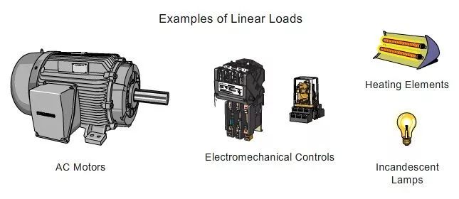
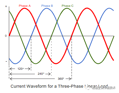
A linear load is any load in which voltage and current increase or decrease proportionately. Voltage and current may be out of phase in a linear load, but the waveforms of each are still sinusoidal and proportionate. Motors, resistive heating elements, incandescent lights, and relays are examples of linear loads. Linear loads can cause a problem in a distribution system if they malfunction or are oversized for the distribution system. However, when operated within specifications, they do not cause harmonic distortion, a type of waveform distortion which will be discussed later.
Power monitoring systems are important for use with all types of loads. For example, they can identify when load currents are approaching levels that will cause an overload and trip overcurrent protection devices.
Power monitoring devices can be used on feeder and branch circuits as well as on distribution system mains. For example, they can be used to monitor individual loads. LEED certification, developed by the U. S. Green Building Council, even requires HVAC and lighting over a certain amperage to be monitored individually for compliance.
Non-linear Loads
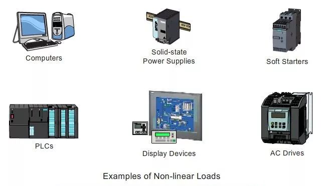
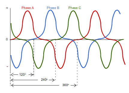
When instantaneous load current is not proportional to instantaneous voltage, the load is considered a non-linear load. Computers, televisions, PLCs, ballasted lighting, variable speed drives, and a variety of devices with electronic power supplies are examples of nonlinear loads.
Non-linear loads can distort waveforms, but the exact amount and type of distortion varies depending on the load. The waveform that you see when you mouse over the red rectangle is only one example of a distorted three-phase current waveform.
A good power quality monitoring systems is essential to maintaining a power distribution system that provides clean power. Applying the wrong solution can be costly and dangerous.
Harmonics
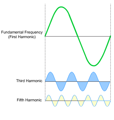
Many electronic circuits and devices produce frequencies which are multiples of the applied frequency. Any frequency produced which is a multiple of the original frequency is called a harmonic.
The original frequency is referred to as the fundamental or base frequency or the first harmonic. Each frequency multiple is referred to by its number. For example, the second harmonic is twice the fundamental frequency, the third harmonic is three times the fundamental frequency, etc.
Circuits that produce harmonics usually produce them at reduced amplitudes from the fundamental frequency. In addition, these circuits do not produce every harmonic multiple, but the specific harmonics produced depend on the type of circuit and the power levels involved.
Harmonic effects can show up as heat in various places such as apparatus neutrals, transformer, and capacitor banks. When the heat builds up sufficiently, equipment is damaged. Power monitoring systems can identify harmonics and their sources to enable corrections.
Inductance and Inductors
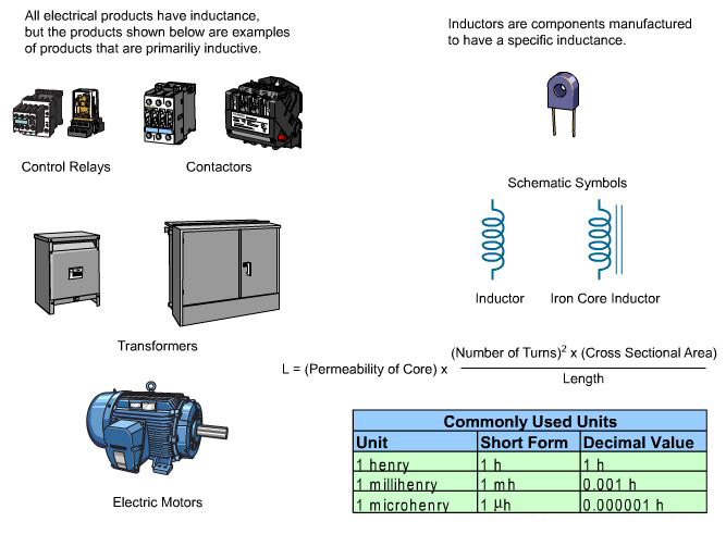
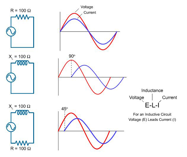
Resistance and voltage are not the only circuit properties that effect current flow. For example, inductance is the property of an electric circuit that opposes any change in electric current. Resistance opposes current flow, but inductance opposes changes in current flow. Inductance is designated by the letter "L". The unit of measurement for inductance is the henry (h).
Current flow produces a magnetic field in a conductor. The amount of current determines the strength of the magnetic field. As current flow increases, field strength increases, and as current flow decreases, field strength decreases.
Any change in current causes a corresponding change in the magnetic field surrounding the conductor. Current is constant for a regulated DC source, except when the circuit is turned on and off, or when there is a load change. However, alternating current is constantly changing, and inductance is continually opposing the change. A change in the magnetic field surrounding the conductor induces a voltage in the conductor. This self-induced voltage, is referred to as counter emf because it opposes the change in current.
All conductors have inductance, but inductors are coils of wire wound for a specific inductance. For some applications, inductors are wound around a metal core to further concentrate the inductance. The inductance of a coil is determined by the number of turns in the coil, the coil diameter and length, and the core material. An inductor is usually indicated symbolically on an electrical drawing as a curled line.
