Inductive Reactance
In a purely resistive AC circuit, resistance is the only opposition to current flow. In an AC circuit with only inductance, capacitance, or both inductance and capacitance, but no resistance, opposition to current flow is called reactance, designated by the symbol X. Total opposition to current flow in an AC circuit that contains both reactance and resistance is called impedance, designated by the symbol Z. Just like resistance, reactance and impedance are expressed in ohms.
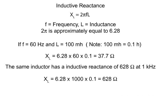
Inductance only affects current flow when the current is changing, but, in an AC circuit, current is changing constantly. Inductance in an AC circuit, therefore, causes a continual opposition to current flow that is called inductive reactance. Inductive reactance is proportional to both the inductance and the frequency applied.
Current and Voltage Phases - Resistive and Inductive Circuits
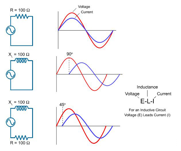
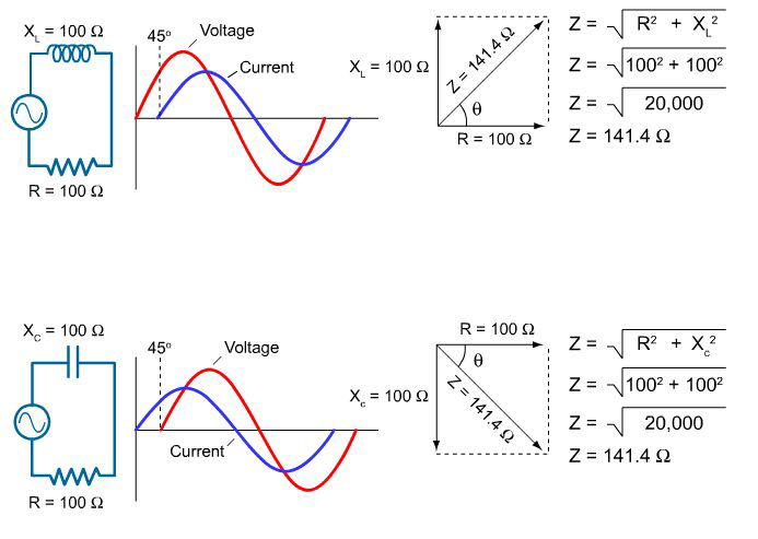
In a purely resistive circuit, current and voltage rise and fall at the same time. They are said to be "in phase." For the circuit in the top illustration, there is no inductance. Therefore, resistance and impedance are the same.
In a purely inductive circuit, voltage leads current by 90 degrees. Current and voltage are said to be "out of phase." For the circuit in the middle illustration, impedance and inductive reactance are the same.
All circuits have some resistance, however, and in an AC circuit with both resistance and inductive reactance, voltage leads the current by more than 0 degrees and less than 90 degrees. For the circuit in the bottom illustration, resistance and inductive reactance are equal and voltage leads current by 45 degrees.
Another way to say this is that current lags the voltage in a circuit with resistance and inductance. The exact amount of lag depends on the relative amounts of resistance and inductive reactance. The more resistive a circuit is, the closer it is to being in phase. The more reactive a circuit is, the more out of phase it is.
Capacitance and Capacitors
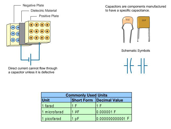
Capacitance is a measure of a circuit's ability to store an electrical charge. A device manufactured to have a specific amount of capacitance is called a capacitor.
A capacitor is made up of a pair of conductive plates separated by a thin layer of insulating material. Another name for the insulating material is dielectric material.
When a voltage is applied to the plates, electrons are forced onto one plate. That plate has an excess of electrons while the other plate has a deficiency of electrons. The plate with an excess of electrons is negatively charged. The plate with a deficiency of electrons is positively charged.
Direct current cannot flow through the dielectric material because it is an insulator; however, the electric field created when the capacitor is charged is felt through the dielectric. Capacitors are rated for the amount of charge they can hold.
The capacitance of a capacitor depends on the area of the plates, the distance between the plates, and type of dielectric material used. The unit of measurement for capacitance is the farad (F). However, because the farad is a large unit, capacitors are often rated in microfarads or picofarads.
apacitive Reactance
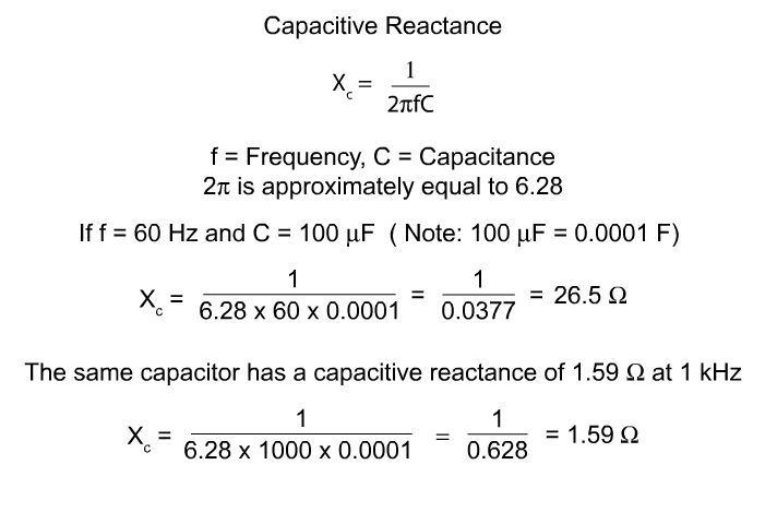
Capacitors also oppose current flow in an AC circuit. This opposition is called capacitive reactance. Capacitive reactance is inversely proportional to frequency and capacitance. Therefore, the larger the capacitor or the higher the frequency, the smaller the capacitive reactance.
Current and Voltage Phases - Capacitive Circuits
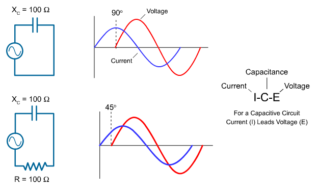
For capacitive circuits, the phase relationship between current and voltage is opposite to the phase relationship for an inductive circuit. In a purely capacitive circuit, current leads voltage by 90 degrees.
In an AC circuit with both resistance and capacitive reactance, current leads voltage by more than 0 degrees and less than 90 degrees. The exact amount of lead depends on the relative amounts of resistance and capacitive reactance. The more resistive a circuit is, the closer it is to being in phase. The more reactive a circuit is, the more out of phase it is.
In the bottom illustration, resistance and capacitive reactance are equal and current leads voltage by 45 degrees.
Impedance
Impedance (Z) is the total opposition to current flow in an AC circuit. Impedance is often represented as a vector. A vector is a quantity that has magnitude and direction.
An impedance vector diagram shows reactance and resistance vectors at right angels to each other with the impedance vector plotted at some angle in between the reactance and resistance vectors. Resistance is plotted at 0 degrees, inductive reactance at 90 degrees, and capacitive reactance at -90 degrees.
The accompanying illustration shows two circuits with equal values of resistance and reactance. The upper circuit has inductive reactance and resistance and the lower circuit has capacitive reactance and resistance.
As shown in the accompanying illustration, The magnitude of the impedance vectors can be determined by taking the square root of the sum of the squares of the reactance and resistance vectors.
Although the magnitude of the impedance vector (141.4 ohms) is the same for both circuits, the angles of the impedance vectors are different. For the upper circuit, the impedance vector has an angle of +45 degrees, but for the lower circuit, the angle is -45 degrees. Note the relationship between the impedance vector angle and the phase relationship between voltage and current for each circuit.
Power in an AC Circuit
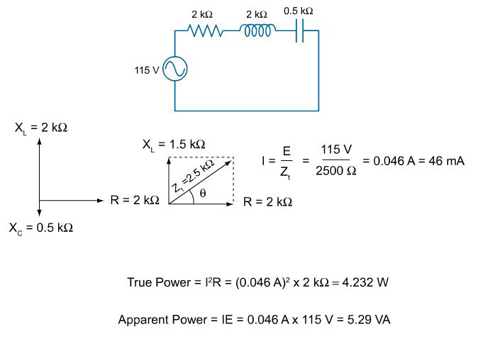
In resistive circuits, power is dissipated in heat. This is called true power or effective power because it is the rate at which energy is used. True power is equal to the current squared times the resistance. The unit for true power is the watt.
Although reactive components do not consume energy, they do increase the amount of energy that must be generated to do the same amount of work. The rate at which this non-working energy must be generated is called reactive power. The unit for reactive power the var (or VAr), which stands for volt-ampere reactive.
The vector sum of true power and reactive power is called apparent power. Apparent power is also equal to the total current multiplied by the applied voltage (P = IE). The unit for apparent power is the volt-ampere (VA).
Power Factor
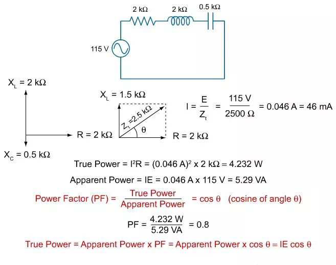
Power factor is the ratio of true power to apparent power in an AC circuit. This ratio is also the cosine of the phase angle.
In a purely resistive circuit, current and voltage are in phase. This means that there is no angle of displacement between current and voltage. The cosine of a zero degree angle is one. Therefore, the power factor is one. This means that all energy delivered by the source is consumed by the circuit and dissipated in the form of heat.
In a purely reactive circuit, voltage and current are 90 degrees apart. The cosine of a 90 degree angle is zero. Therefore, the power factor is zero. This means that all the energy the circuit receives from the source is returned to the source.
For the circuit in the accompanying illustration, the power factor is 0.8. This means the circuit uses 80 percent of the energy supplied by the source and returns 20 percent to the source.
Another way of expressing true power is as the apparent power times the power factor. This is also equal to the current (I) times the voltage (E) times the cosine of the phase angle.
Voltage Variations
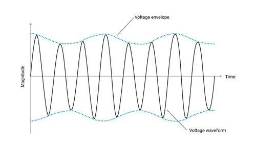
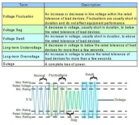
Even the best distribution systems are subject to periodic changes in system voltage. Voltage changes can range from small voltage fluctuations of short duration to a complete outage for an extended period of time. The following industry terms are used to describe various voltage conditions.
Sags and undervoltages can result when high current loads, such as large motors, are started. Undervoltage is also commonly caused by overloaded transformers or improperly sized conductors. Undervoltage may also occur when a power utility reduces the voltage level to conserve energy during peak usage.
Swells and overvoltage can result when high current loads are switched off, such as when machinery shuts down. Overvoltage may occur on loads located near the beginning of a power distribution system or where there are improperly set voltage taps on a transformer secondary.
Short duration variations, sags and swells, typically last less than 1 minute; whereas, undervoltages and overvoltages are longer in duration. Common sags and swells occur from faults, motor starting, or the operation of the power company's protective equipment.
Voltage Unbalance
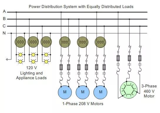
Voltage unbalance occurs when the phase voltages in a three-phase system are not equal. One possible cause of voltage unbalance is the unequal distribution of single-phase loads.
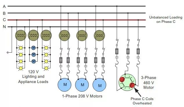
In the illustration that you see when your mouse is not over the red rectangle, the loads are balanced. Mouse over the rectangle to see an example of a system with unbalanced loading. In this example, additional lighting and small appliance loads are connected to phase C. This has caused the voltage on phase C to be lower.
Because a small unbalance in voltage can cause a high current unbalance, in this example, overheating has occurred in the C phase winding of the 3-phase motor. In addition, the single-phase motors connected to phase C are operating on a reduced voltage. These loads may also experience overheating problems.
Importance of Power Factor
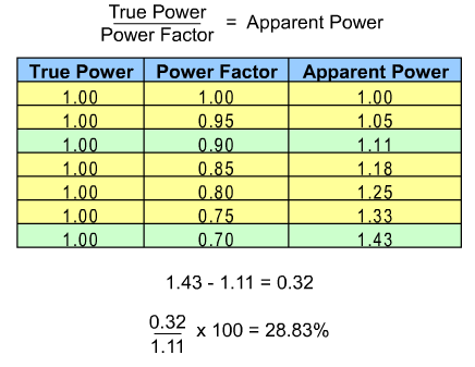
Like the power quality issues discussed on the previous pages, power factor also affects the cost of doing business. In the case of power factor, however, the impact is immediate. The lower the power factor for a company's power distribution system, the more electricity that company has to buy, all other things being equal.
For example, as the accompanying chart shows, if a power distribution system has a power factor of 0.7, it requires nearly 29% more power for each unit of true power than if it had a power factor of 0.9.
In addition, a power distribution system has to be capable of handling greater current if it has a low power factor than if it had a higher power factor. This means that if power factor drops, greater strain is placed on a company's power distribution system. This often results in increased maintenance cost.
Because power factor depends on the equipment and processes in operation at a specific time, power factor must be constantly monitored and controlled to control business operating costs.
