High reliability, designed particularly for Industrial Loads
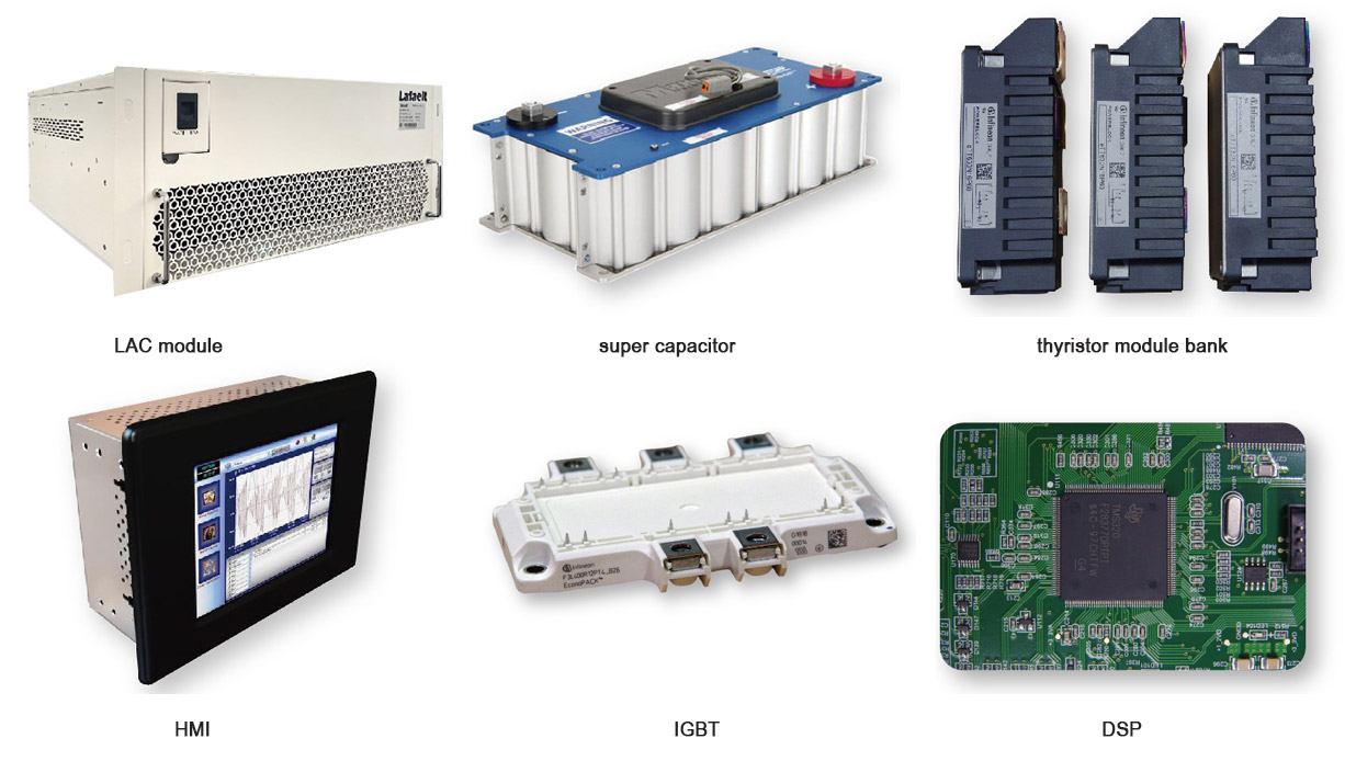
Distributed control system, truly realize N+1 redundancy
Superior rectifier inverter performance, no harmonic injection
HMI adopts windows-level system, which can complete the data records arbitrarily and flexible monitoring
It adopts advanced patented phase-locked loop control algorithm, fast tracking frequency disturbance and resulted in small frequency tracking accuracy error while ensuring no corresponding sudden changes in load voltage when compensating and exiting
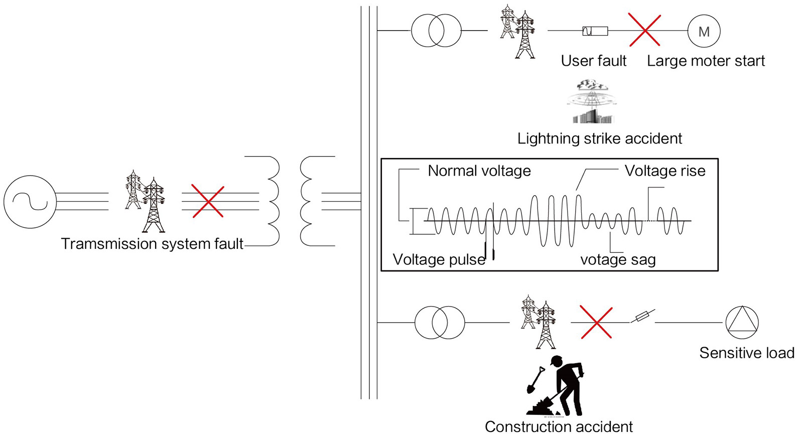
At present, among various power quality problem, voltage sag is the problem with the highest frequency and the most serious harm.
The most common causes of voltage sag are as follows:
When a short-circuit fault occurs in the transmission network or the distribution network, the current increases sharply, causing a voltage sag at the public voltage connection point, and the voltage sag spreads along the gird to cause disturbance to a large number of users.
When the induction motor is started at full voltage, the voltage value that needs to be drawn from the system is 5-10 times that of the full load operation, this large current will cause a voltage sag when it flows through the system impedance.
Insulator flashover and line-to-ground discharge caused by lightning strikes are the main causes of system line voltage drop. In the rainy season or in thunderous areas, operating equipment exposed to the open air is easily disturbed by lightning

DVR is currently recognized as an effective series compensation device for keeping the supply voltage of sensitive loads stable. When the system voltage sags or rises suddenly, it uses its own energy storage and inverter devices to output voltages with adjustable phase and amplitude to ensure that the voltage of sensitive loads is still within an acceptable range when disturbed by the system voltage
If the power grid is in a stable state and runs in thermal backup mode, the bidirectional DC/AC inverter controls the charging current through a control algorithm to keep the system in a floating charge state, while the DVR continuously detects the grid voltage. When the voltage drops, the algorithm can detect it within 500us, and quickly control the switch to shut off, cut off the input grid voltage, make the DVR to operate in the compensation output mode, absorb the energy stored in its own super capacitor, inject the AC voltage into the system through the inverter which is consistent with the phase and amplitude of the grid voltage before the drop, and provide high-quality power for sensitive loads in a short time. After the grid voltage recovers, the DVR controls the conduction of the bidirectional thyristor through the control algorithm to realize seamless switching to the grid voltage.

a.The three-phase drop to 0%, the overall waveform of the grid voltage and load voltage, the upper part of the picture is load voltage, and the lower part is gird voltage.
b.The three-phase drop to 0%, the waveform of the grid voltage
c.The three-phase drop to 0%, the waveform of the load voltage
d.The instantaneous detailed waveform of entering voltage compensation, and the time is within 2ms.

1.Automobile manufacturing, painting, etc. flexible automatic control and chain supply line management
2.Polymerization processing industry of plastic products, paper industry, glass manufacturing industry, chemical industry-big power consumers
3.IT and Communication Industry-High-value end customers need ultra-high reliability
4.Medical equipment—the sag causes the equipment to work abnormally, affecting the diagnosis, treatment, operation, and even endangering the life of the patient

5.In the semiconductor manufacturing industry, a short-term voltage sag will cause the produced chips to become defective products, resulting in huge losses
6.Widely used in the precision processing industry, the microprocessor of the control system of the equipment is particularly sensitive to voltage sags
7.Most contactor and relay manufacturers specify a loss of voltage protection of 0.5p.u., which will exit and disconnect if the duration exceeds 1 cycle
8.When the voltage drop depth supplied to the induction motor is greater than 30%, the electromagnetic torque will be smaller than the mechanical torque, the motor speed will decrease, and the current drawn will increase
1. Wide voltage compensation range: When the system has high and low voltages of 0~130% p.u., it can ensure the constant voltage of the load side
2. Fast response speed: the response speed of the whole machine is less than 2ms, which meets the requirements of any load
3. Strong impact resistance: the impact current within 5 times of the load has no effect on DVR
4. High efficiency: the efficiency of the whole machine is greater than 99%, saving electricity costs
5. Long life and maintenance-free: the design life of the whole machine is more than 15 years, and there is no need for maintenance in the whole process
6. Overload capacity: at 150% of the rated capacity, it can be maintained for 60S
7. Small footprint: one-fifth of the same capacity UPS
Voltage level | 208V 400V 690V 10KV |
Rated capacity | 50kVA-5000kVA |
Compensation range | 0%-130% |
Compensation time | 0.4-30s (time can be customized) |
Continuous voltage sag protection | CAN |
Working frequency | 50/60Hz±10% |
Efficiency | 99.2% |
Overload and short-circuit protection | Breaker |
Overload capacity | Thyristor overload 150%, maintain 60s, overload 500%, maintain 1s |
Three-phase grid type | Three-phase three-wire / three-phase four-wire |
Compensation voltage settings | CAN |
Compensation action threshold settings | CAN |
Output frequency | 50/60Hz±10% |
Voltage compensation accuracy error | <1% |
Voltage distortion ratio THDU | On linear load condition <3% |
Voltage imbalance | On 100% unbalanced load condition <3% |
Voltage compensation response time | Less than 2ms |
Response time | 50us |
Load power factor | 0.5 lag to 0.9 lead |
Energy storage component | Super capacitor |
Working temperature | -25~+45℃ |
Charge and discharge cycle number | >1,000,000 times |
Designed life span | 15 years (25℃) |
Overload capacity | 200% |
Re-charge time | <45s |
Measurement method | Phase-voltage / line voltage |
Event resolution | 10ms |
Detection period | 50us |
Interface | RS485、CAN |
Protocol | Modbus |
HMI | 8 inch or above touch screen |
Failsafe bypass | Bypass contactor |
Maintenance bypass | Bypass breaker |
Cooling | Forced air cooling |
Noise(dB) | <40 |
Working temperature | -25~45℃(above 45℃, derating 2% for every 1℃rising) |
Operation humidity | 0-95% no gel |
Working altitude | 0-3000m(>2000m, derating 1% for every 100m rising) |
Protection class | IP21 or IP23, other class can be optional |
Model | Capacity | Dimension | Voltage Grade |
LAC-100-04-N-3 | 100KVA | 800*1000*2200 | 0.4KV |
LAC-150-04-N-3 | 150KVA | 800*1000*2200 | 0.4KV |
LAC-150-04-N-3 | 150KVA | 1400*1000*2200 | 0.4KV |
LAC-200-04-N-3 | 200KVA | 1400*1000*2200 | 0.4KV |
LAC-300-04-N-3 | 300KVA | 1400*1000*2200 | 0.4KV |
LAC-400-04-N-3 | 400KVA | 2800*1000*2200 | 0.4KV |
LAC-500-04-N-3 | 500KVA | 2800*1000*2200 | 0.4KV |
LAC-600-04-N-3 | 600KVA | 2800*1000*2200 | 0.4KV |
LAC-750-04-N-3 | 750KVA | 4200*1000*2200 | 0.4KV |
LAC-900-04-N-3 | 900KVA | 4200*1000*2200 | 0.4KV |
LAC-1050-04-N-3 | 1050KVA | 5600*1000*2200 | 0.4KV |
LAC-1200-04-N-3 | 1200KVA | 5600*1000*2200 | 0.4KV |
LAC50-02-N-3 | 50KVA | 800*1000*2200 | 0.2KV |
LAC75-02-N-3 | 75KVA | 800*1000*2200 | 0.2KV |
LAC100-02-N-3 | 100KVA | 1400*1000*2200 | 0.2KV |
LAC150-02-N-3 | 150KVA | 1400*1000*2200 | 0.2KV |
LAC200-02-N-3 | 200KVA | 2800*1000*2200 | 0.2KV |
LAC300-02-N-3 | 300KVA | 2800*1000*2200 | 0.2KV |
LAC375-02-N-3 | 375KVA | 4200*1000*2200 | 0.2KV |
LAC450-02-N-3 | 450KVA | 4200*1000*2200 | 0.2KV |
LAC600-02-N-3 | 600KVA | 5600*1000*2200 | 0.2KV |

| Classify | Title | Download |
|---|
Leave your contacts and our engineers will help you to find the solution you are looking for.

Hi! Welcome back.
How are you doing?
Let s talk! We’ll provide the perfect solution for you!

Since its establishment, Lafaelt Electric has focused on comprehensive solutions for power quality and energy management. It has excellent quality in designing, researching, producing and manufacturing.
Sales Center Add: 2nd Floor, No. 268, Tongxie Road, Changning District, Shanghai, China
Factory Add:No. 79, Qunxing Road, Xinwu District, Wuxi City, Jiangsu Province, China